Introduction to Digital Design
Schematics due Mon Oct 23rd by 11:59pm in your Lab04 GitHub repo
Background
We are now learning the basics of digital logic and digital circuits with the goal of learning enough to build a working computer processor. We will use the Digital application to build and simulate digital circuits: https://github.com/hneemann/Digital. For this lab your are going to build and simulate some simple circuits.
Part 1: LEDs
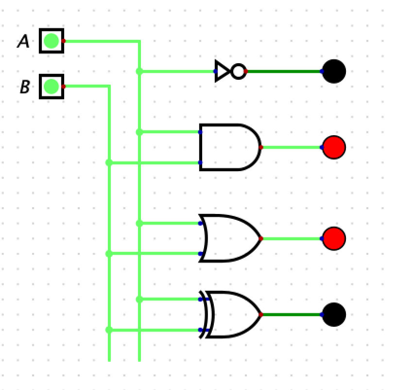
- You will build a circuit in with two inputs and 4 LED output that shows how 4 basics gates work: NOT, AND, OR, and XOR.
- The LED will turn red when the input is high (1) and black when in the input is low (0).
- Here is a screen shot of the circuit you need to build and simulate. Note that you need to add labels to the inputs (A and B):
Part 2: Max2
Consider the C code fragment below:
if (a > b) {
    r = a;
} else {
    r = b;
}
- We will assume that a, b, and r are 2-bit values. That is, the only values a, b, and r can be are 0, 1, 2, or 3.
- Your job is to use sum-of-products to come up with a Boolean algebra equation and a circuit that will compute the max value r (which is also a 2-bit value).
- Your inputs will be
a1,a0,b1,b0and your outputs will ber1andr0. So, you will have two Boolean equations, one forr1and one forr0. - Since there are 4 inputs you will have 2^4 (16) rows in your truth table.
- Submit a working circuit that correctly produces the max value of the two inputs. You do not need to submit the truth table or Boolean algebra equation.
- Your circuit must have input names
a1,a0,b1, andb0. The file must be calledmax2.dig
Part 3: 1-bit full adder
- In lecture, we built a 1-bit half adder (that is, an adder which does not have a carry-in) and showed the Boolean Algebra equation for a 1-bit full adder.
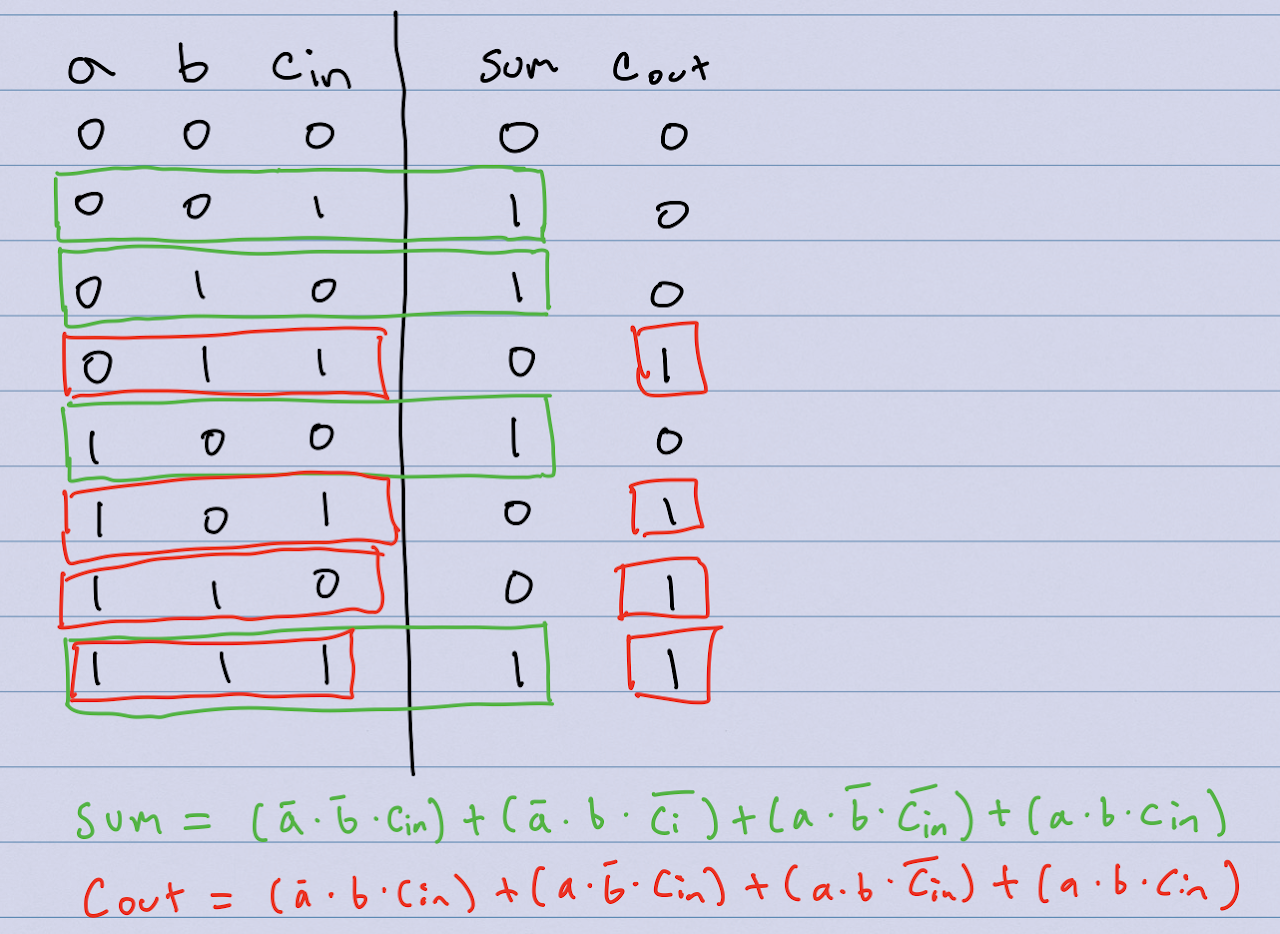
- You will build a 1-bit full adder in Digital, including a carry-in (
cin) and a carry-out (cout). Your circuit must have inputs nameda,b, andcin, and outputs namedsumandcout. Your file must be named1-bit-full-adder.dig - Here are the truth table and sum-of-products equations for
sumandcout
Part 4: 8-bit Ripple Carry Adder
- You will implement an 8-bit Ripple Carry Adder with two 8-bit inputs, a 1-bit Carry In, one 8-bit result output, and a 1-bit Carry Out.
- Your circuit must have inputs named
a,b, andcin, and outputs namedsumandcout. Your file must be called8-bit-ripple-carry-adder.dig
Rubric
- 33 pts: max2
- 33 pts: 1-bit full adder
- 34 pts: 8-bit full adder
- The LED circuit is just a warmup and will not be graded